
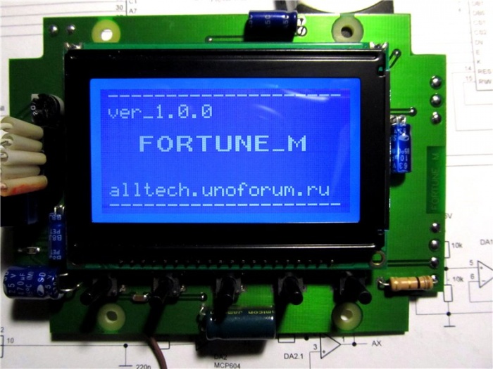
Best Metal Detector
Why was Volksturm called the best metal detector? The main thing is the scheme really simple and really working. From a variety of metal detectors schemes that I personally did, it is here that everything is simple, deep and reliably! Moreover, with its simplicity, there are in the metal detector good scheme Discrimination - the definition of iron or non-ferrous metal is in the ground. The assembly of the metal detector consists in an error-free solder of the board and setting the coils into the resonance and at zero at the output of the input stage on the LF353. There is nothing superser, there would be a desire and brains. We look constructive metal detector execution and a new enhanced Volksturm scheme with a description.
Since, in the course of the assembly, questions arise to save your time and not to force the hundreds of pages of the forum, here are answers to the 10 most popular questions. The article in the process of writing, so some items will be supplemented later.
1. Principle of operation and detecting the goals of this metal detector?
2. How to check whether a metal detector work works?
3. What resonance to choose?
4. What condensers are better?
5. How to set up resonance?
6. How to cut coils in zero?
7. What wire for coils is better?
8. What are the details and what can be replaced?
9. What is the depth of the search for goals?
10. Nutrition of the Volksturm Metal Detector?
The principle of operation of the Volksturm Metal Detector
I will try in two words about the principle of operation: transmission, reception and balance of induction. In the search sensor of the metal detector, 2 coils are installed - transmitting and receiving. The presence of a metal changes the inductive link between them (including phase), which affects the received signal, which is then processed by the indication unit. Between the first and second chip, the switch controlled by the generator shifted by phase relative to the transmitting channel (i.e., when the transmitter works, the receiver is turned off and on the contrary if the receiver is turned on the transmitter rests, and the receiver calmly catches the reflected signal in this pause). So, you turned on the metal detector and it beeps. Excellent, if stamps - it means many nodes work. Let's figure out why it is stamping. The U6B generator constantly generates a tone. Next, it enters the amplifier on two transistors, but the UHH will not open (will not miss the tone) until the voltage at the y2B (7th output) will not allow it. This voltage is set by changing the mode using this very resistor TRACH. They need to set such tension so that the UHR almost opened and missed the signal from the generator. And the input pair of Milvololt from the metal detector coil, passing the amplifying cascades, will exceed this threshold and it will open completely and the speaker will be discovered. Now let's follow the passage of the signal, or rather the response signal. At the first cascade (1-U1A) there will be a pair of Milcivolt, you can up to 50. On the second cascade (7-U1B), this deviation will increase, on the third (1-U2) will already be a couple of volts. But without a response everywhere at the outputs at zeros.
How to check whether the board is working

In general, the amplifier and key (CD 4066) is checked with a finger at the RX input contact with the maximum Sens resistance and the maximum background on the dynamics. If there is a change in the background when you press a finger for a second, the key and the operatives work, then connect the RX coils with the circuit condenser in parallel, the condenser on the TX coil sequentially, we give one coil to another and start to reduce 0 at a minimum indication alternating current On the first leg of the amplifier U1A. Next, we take something big and iron and check there is a reaction to metal in the dynamics or not. We will check the voltage on the U2B (7th output) it should be a trash regulator, change + volt. If not, the problem is in this Cascade of OU. To start checking the board, turn off the coil and turn on the power.
1. Must go sound when the sensor regulator is positioned on the maximum resistance, totto the finger on the Px - if there is a reaction, all the operatingors work, if not, we check the finger starting with U2 and change (survey the strapping) of non-working OU.
2. The generator operation is verified by the frequency meter program. Plug from headphones soldered to 12 withdrawal CD4013 (561TM2) prudently dropping P23 (so sound card Do not burn). In the sound card to use in-lane. We look at the generation frequency, its stability is 8192 Hz. If it is strongly shifted, then the C9 capacitor should be harvested, if after it is not clearly highlighted and / or a lot of frequency bursts nearby - replace quartz.
3. Checked amplifiers and generator. If everything is fine, but still does not work - change the key (CD 4066).
What resonance to choose

When connecting the coil into a serial resonance, the current in the coil and the overall consumption of the circuit increases. Increases the distance detection distance, but it is only on the table. On the real soil, the earth will feel the stronger than the larger the pumping current in the coil. It is better to turn on parallel resonance, and raise the input cascades. Yes, and the batteries are enough much longer. Despite the fact that consistent resonance is used in all branded expensive metal plates, in the storm you need it precisely parallel. In imported, expensive devices, good configuration schematics from the ground, therefore, in these devices can be allowed to be allowed.
What condensers are better to install in the scheme metal detector

The type of capacitor connected to the coil is not when, and if it was experimentally changed two and saw that with one of them the resonance is better, then it is simply one of the supposedly 0.1 μF really has 0.098 Igf, and the other 0.11. So the difference between them in resonance is obtained. I used Soviet K73-17 and green imported pillows.
How to set up resonance coils metal detector

Coil like the most the best wayIt turns out of plastering grads glued with epoxy resin from the ends to the size you need. Moreover, its central part with a piece of the handle of this very grater, which is processed to one wide ear. On the bar, on the contrary, the fork of two bunches of fastening. This solution allows you to solve the problem of deformation of the coil, when tightening the plastic bolt. The windings for the windings make the usual delicate, then setting the zero and fill. From the cold end TX, we will leave 50 cm. Wires, which originally not to fill, and press the small coil from it (with a diameter of 3 cm) and place it inside the RX, moving and deforming it in small limits, you can achieve an accurate zero, but to do it It is better on the street by placing the coil at the Earth (as when searching) with the geb disconnected if it is, then finally pour the resin. Then the detuning from the Earth, it works more, less tolerable (the exception is strongly mineralized soil). Such a coil is obtained easy, durable, little prone to thermodood, and treated and painted very pretty. And one more observation: if the metal detector is assembled with downtown (GEB) and under the central location of the resistor's engine to set zero a very small washer, the geba adjustment range is 80-100 mV. If you set the zero large subject of a coin 10-50 kopeck. The adjustment range increases to + - 500-600 mV. During the voltage in the process of adjusting the resonance, do not chase - I have about 40V with 12V power sequential resonance. To discriminate, condensers in the coils turn on in parallel (the sequential inclusion is only needed at the selection stage for resonance) - on ferrous metals there will be a long sound, color - short.
Or even easier. We connect the coils in turn to the transmitting TX output. We configure one in the resonance, and configuring it - another. Step by step: they connected, parallel the coil was twisted by a multimeter at the limit variables, the condenser 0.07-0.08 ICF soldered the coil parallel to the coil, see the testimony. Suppose 4 V is very weak, not in resonance with a frequency. Pressed parallel to the first condenser of the second small capacity - 0.01 μF (0.07 + 0.01 \u003d 0.08). We look - already showed a voltmeter 7 V. Excellent, we will increase the container, connect to 0.02 μF - we look at the voltmeter, and there are 20 V. Great, we are going on - another dock is a couple of thousand peaks of tanks. Yeah. Already the beginning fall, roll up back. And so to achieve maximum voltmeter readings on a metal detector coil. Then, similarly on the other (reception) coil. Configure maximum and connect back to the receiving socket.
How to reduce metal dealer coils in zero

To adjust zero, we connect the tester to the first leg LF353 and we begin to compress, stretch the coil. After the epoxy bay - Nolik will definitely run away. Therefore, it is necessary to pour not the whole coil, but leave space for adjustment, and after drying, bring to zero and pour finally. Take a piece of twine and half the coil to tie in one turn to the middle (to the central part, the place of connecting two coils) insert a piece of a piece of sticks after which it is twisted (pulling the twine) - the coil will shrink, catching the spike sponge to be impregnated with glue Again, to adjust the nolik by turning the wand more slightly and pour the twine finally. Or easier: the transmitted is fixed in plastic stationary, and the reception is superimposed on the first 1 cm, such as wedding rings. At the first pin, U1a will be a peak of 8 kHz - can be controlled by a voltmeter of alternating current, but better just high-level headphones. So the receiving coil of the metal detection must be shifted, then shifted with transmitting until the output of the OU does not appeal to a minimum (or the testimony of the voltmeter will not fall to several milcialt). Everything, the coil is reduced, fix.
Which wire for search coils is better

Wire for winding coils does not matter. From 0.3 to 0.8 there will be any, it will still have to pick up the capacitance to adjust the contours to the resonance and the frequency of 8.192 kHz. Of course, a thinner wire is quite suitable, just what it is thicker, the kindness and, as a result of a little - better. But if you wind 1 mm - it will be quite hard to carry. On a sheet of paper, we draw a rectangle 15 to 23 cm. From the left upper and lower angle, we deposit 2.5 cm, and connect their line. We also do the same with the right top and bottom corners, but we post 3 cm. In the middle of the bottom we put the point and on the point left and right at a distance of 1 cm. We take Phaneur, we put this sketch and drive the carnations to all points specified. We take the wire of the PEV 0.3 and wind 80 turns of the wire. But honestly, no difference how many turns. All the same, the frequency of 8 kHz will be exhibited in a condenser resonance. How many wounds - so much wound. I wind 80 turns and a condenser 0.1 of the ICF, if you wog up 50 - the container, respectively, somewhere 0.13 μF will have to have. Next, without removing from the template, wind the coil is thick thread - such as wiring harnesses. After covering the coil with varnish. When dried, remove the coil from the template. Then there is a winding of the coil with insulation - FUM tape or tape. Next is the winding of the foil coil of the coil, you can take a ribbon from electrolytic capacitors. TX The coil can not be shielded. Do not forget to leave the gap in the screen 10 mm, in the middle of the coil. The foil winding is on the tinned wire. This wire, along with the initial contact of the coil, we will have a mass. And finally winding the coil with a tape. The inductance of coils is about 3.5 mg. Capacity is about 0.1μF. As for the fill of the coil epoxy, I did not stick it at all. Just tightly climbed the tape. And nothing, two seasons went away with this metal detector without setting. Pay attention to the moisture insulation of the circuit and search coils, because you will have to mock the grass. Everything should be hermetically - otherwise the moisture will fall and the setting will float. Worsen sensitivity.
What details and what can be replaced

Transistors:
BC546 - 3pcs or kt315.
BC556 - 1pc or kt361
Operations:
LF353 - 1pcs or change to a more common TL072.
LM358N - 2pcs
Digital microcircuits:
CD4011 - 1pc
CD4066 - 1pc
CD4013 - 1pc
Resistors permanent, Power 0.125-0.25 W:
5.6K - 1pc
430K - 1pc
22K - 3pcs
10K - 1pc
390K - 1pc
1k - 2pcs
1.5K - 1pc
100K - 8pcs
220K - 1pc
130K - 2pcs
56k - 1pc
8.2K \u200b\u200b- 1pc
Resistors variables:
100K - 1pc
330K - 1pc
Capacitors are notolar:
1NF - 1pc
22nf - 3pcs (22000pf \u003d 22nf \u003d 0.02222222222
220NF - 1pc
1MKF - 2pcs
47NF - 1pc
10nf - 1pc
Electrolytic condensers:
220MKF on 16V - 2pcs
The dynamic miniature.
Quartz resonator on 32768 Hz.
Two supermarket LEDs of different color.
If you can not get imported chips, here are the domestic analogues: CD 4066 - K561T3, CD4013 - 561TM2, CD4011 - 561L7, LM358N - kr1040ud1. The LF353 chip is there is no direct analogue, but boldly put LM358N or better TL072, TL062. Not necessarily install operational amplifier - LF353, I just raised the reinforcement on the U1A replacing the resistor in the negative chain feedback 390 com per 1 mΩ - sensitivity increased significantly by percentage of 50, though after this replacement went zero, I had to glue the coil in a certain place to glue a piece of aluminum plate. Soviet three kopecks feels over the air at a distance of 25 centimeters and this is 6 volts when nutrition, the current consumed without indication is 10 mA. And do not forget about the panels - convenience and simplicity settings will increase significantly. CT814 transistors, KT815 - to the transmitting part of the metal detector, CT315 in UH. Transistors - 816 and 817 It is desirable to choose with the same gain coefficient. Replace on any appropriate structure and power. In the metal detector generator, a special hour quartz is installed at a frequency of 32768 Hz. This standard is absolutely for all quartz resonators, which are in any electronic and electromechanical clock. Including wrist and cheap Chinese wall / desktops. Archives S. pCB For the option and for (an option with manual detuning from the Earth).
What depends the depth of the search for goals
The greater the diameter of the metal dealer coil, the more deeply. In general, the depth of detection of the target with this coil depends primarily on the size of the target itself. But with an increase in the diameter of the coil, there is a decrease in the accuracy of the detection of the object and even sometimes loss of small goals. For objects with a coin, this effect is observed with an increase in the coil size over 40 cm. Total: a large search coil, has a greater depth of detection and greater capture, but less accurately detects the target than the small one. The big coil is ideal for finding deep and large goals, such as treasures and large objects.
The coil shape is divided into round and elliptic (rectangular). The elliptical coil of the metal detector has the best selectivity compared to the round, because it is less than the width of the magnetic field and there are less extraneous objects in its field. But the round has a greater depth of detection and better sensitivity to the goal. Especially on weakly mineralized soils. The round coil is most often used when searching with a metal detector.
The coils with a diameter of less than 15 cm are called small, the coil with a diameter of 15-30 cm is called medium and coils over 30 cm - large. The big coil generates a greater electromagnetic field, so it has a large detection depth than small. Big coils generate a large electromagnetic field and, accordingly, have a greater depth of detection and coating when searching. Such coils are used to view large areas, but when using them, there may be a problem on highly messenger sites because in the field of the action of large coils can be caught several goals and the metal detector will react to a larger goal.
Electromagnetic field small search coil Also small, so it is best to search with such a coil in the territories highly litouced by all sorts of small metal objects. The small coil is ideal for detecting small objects, but has a small area of \u200b\u200bcoating and a relatively small detection depth.
For universal search, medium coils will fit well. This search coil size combines a sufficient depth of search and sensitivity to goals with different sizes. I made every coil with a diameter of about 16 cm and both of these coils laid in a round stand from under the old monitor 15. "In this embodiment, the depth of this metal detector will be the following: aluminum plate 50x70 mm - 60 cm, nut M5-5 cm, coin - 30 cm, bucket - near the meter. These values \u200b\u200bare obtained in air, in the ground will be 30% less.
Metal detector power
Separately, the metal detector scheme pulls 15-20 mA, with a connected coil + 30-40 mA, and there is up to 60 mA. Of course, depending on the type of dynamics used and LEDs, this value may vary. The simplest case - the power took 3 (or even two) consistently connected lithium ion batteries from Mobile by 3.7V and during charge of discharged batteries, when you connect any power supply to 12-13V, the charge current starts from 0.8A and drops to 50m An hour and then do not need to add something at all, although the restrictive resistor of course does not prevent. As general, the most simplest option - Krona on 9V. But note that the metal detector will eat it in 2 hours. But to configure this power option. Crown under any circumstances will not give a large current that can burn something in the board.
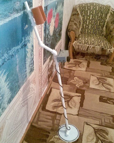
Homemade metal detector

And now a description of the metal detector assembly process from one of the visitors. Since I have only a multimeter from the devices, I downloaded the virtual laboratory of records OL. Assemmed the adapter, a simple generator and drove into a single oscilloscope. It seems like some picture. Next, I started searching for radio components. Since the sizes are mostly laid out in the "Lay" format, Sprint-layout50 downloaded. I found out that such a laser and ironing technology of manufacturing printed circuit boards and how to train them. Put the board. By this time, all microcircuits were found. What I did not find in my shed, I had to buy. I began to solder jumpers, resistors, microcircuit sockets, and quartz from the Chinese alarm clock on the fee. Periodically checking the resistance on the power tires so that no snotes were. I decided to start collecting the digital part of the device as the easiest. That is a generator, divider and switch. Collected. Put the generator chip (K561L7) and the divider (K561TM2). B / ear microcircuits, out of some boards discovered in the shed. Submitted power 12V controlling current consumption by amermeter, 561TM2 became warm. Replaced 561TM2, filed food - zero emotions. We measure the voltage on the legs of the generator - on 1 and 2 legs of 12V. I change 561l7. I turn on - at the exit of the divider, there are generation on 13 legs (I observe on a virtual oscilloscope)! The truth is not so good, but for the absence of a normal oscilloscope - will go. But on 1, 2 and 12 legs there is nothing. So the generator works, you need to change TM2. Installed the third chip of the divider - beauty at all outputs is generation! For myself, I concluded that the chips need to be filled as careful! This is the first step of the building made.
Now configure the metal detector's fee. The "SENS" regulator did not work - sensitivity, I had to throw out the C3 capacitor after that the sensitivity adjustment earned as it should. I didn't like the sound that occurs in the extreme left position of the "Thresh" regulator - threshold, got rid of this replacing the resistor R9 with a chain of a successively connected resistor by 5.6 kΩ + condenser by 47.0 μF (negative condenser withdrawal from the transistor). While there is no LF353 chip instead of her LM358, the Soviet three kopecks feels with it at a distance of 15 centimeters.

I turned on the search coil on the transmission as a sequential oscillating circuit, and on the reception as a parallel oscillating circuit. Called the first transmitting coil, connected the collected design of the sensor to the metal detector, the oscilloscope parallel to the coil and at the maximum amplitude, the capacitors picked up. After that, the oscilloscope connected to the receiving coil to the receiving coil and at the maximum amplitude, the condensers were picked up on RX. The adjustment of the contours in the resonance takes, in the presence of an oscilloscope, a few minutes. TX and RX windings in me contain 100 turns of the wire with a diameter of 0.4. We start mixing on the table, without a case. Just so that there were two wrap with wires. And to make sure that work and the possibility of information is generally - the collapse of the coil from the DRA half the meter. Then zero will be accurate. Then impoverish the coil of the flask about 1cm (as wedding rings) shift - to move away. The zero point can be quite accurate and catch it immediately difficult. But it is.

When, I raised the reinforcement in the RX path of MD, he began to work unstable on the maximum sensitivity, this was manifested that after passing over the goal and its detection was given a signal, but it continued and after the goals before the search coil did not have any manifested in the form of intermittent and oscillating sound signals. With the help of an oscilloscope, the reason for this was found: during the operation of the dynamics and a minor feeding drawdown of the supply voltage, "zero" and the MD scheme goes into an auto-oscillating mode, to exit from which you can only download the triggering threshold. It did not suit me therefore I put the meal of kr142en5a + over bright white LED To raise the voltage at the output of the integral stabilizer, the stabilizer to more high voltage I did not have. Such an LED can be used even to illuminate the search coil. The speaker connected to the stabilizer, MD after that it became immediately very obedient all began to work as it should. I think Volksturm is really the best homemade metal detector!
Recently, this scheme has been proposed, which will allow us to turn Volksturm S in Volksturm SS + GEB. Now the device will have a good discriminator as well as the selectivity of metals and tuning from the soil, the device rolls on a separate board and is connected instead of C5 and C4 capacitors. The scheme of refinement and in the archive. Separate thanks for information on the assembly and configuration of the metal detector to everyone who participated in the discussion and modernization of the scheme, especially helped in the preparation of the material of the electrocity, festka, XXX, SLAVAKE, EW2BW, REDKII and other radio amateurs colleagues.
What is the metal detector to explain to anyone. The device is dear, and some models are quite decent.
However, you can make the metal detector with your own hands at home. Moreover, you can not only save thousands of rubles on its acquisition, but also to get rich, finding a treasure. Let's talk about the appliance itself and try to figure out what in it and how.
Step-by-step instruction for assembling a simple metal detector
In this detailed instruction, we will show how you can collect the simplest metal detector from the remedies. We will need: a plain plastic box from a CD disc, portable AM \u200b\u200bor AM / FM radio, calculator, VelCro contact tape (velcro). So, proceed!
Step 1. Disassemble CD CD Box CD. Carefully disassemble the compact disc plastic box, remove the insert that holds the disk on the spot.
Step 1. Removal of plastic insert from SidiboxStep 2. Cut 2 velcro strips. Squeeze the area in the center of the rear of your radio. Then cut 2 pieces of velcro of the same size.
 Step 2.1. Memore approximately in the middle area on the back of the radio (highlighted in red)
  Step 2.2. Cut 2 velcro of the corresponding size measured in step 2.1
 Step 3. Secure the radio. Attach one velcro on the back of the radio and second to one of the inner sides of the CD box. Then attach the radio on the body of the plastic box of the CD "Velcro to Velcro".


Step 4. Secure the calculator. Repeat steps 2 and 3 with a calculator, but apply the velcro on the other side of the CD box. Then secure the calculator on this side of the box with the standard Velcro method.

Step 5. Setting Radio Range. Turn on the radio and make sure it is configured to AM Range. Now adjust it to the end of the AM range, but not to the radio station itself. Increase the volume. You must only hear some interference.

Prompt:
If there is a radio station, which is at the very end of the AM range, then try to get to it as close as possible. At the same time, you should hear only some interference!
Step 6. Roll the CD box. Turn on the calculator. Start turning the side of the box with the calculator towards the radio until you hear a loud beep. This beep signals us that the radio caught the electromagnetic wave from the electrical circuit of the calculator.
 Step 6. We are folding the parties CD boxing to each other until the characteristic loud signal is heard.
 Step 7. Subcontalize collected device to a metal object. Open the flaps of the plastic box again, so that the sound we heard in step 6 is barely heard. Then start moving the box with your radio and the calculator close to the metal object and you again hear a loud sound. This indicates the correct work of our simplest metal detector.

Instructions for assembling a sensitive metal detector based on a two-circuit oscillator scheme
Operating principle:
In this project, we will build a metal detector based on the dual circuit of the oscillator. One oscillator is fixed, and the other varies depending on the proximity of metal objects. The frequency of the beats between these two frequencies of oscillators is in the sound range. At the time of the detector over the metal object, you will hear a change in this frequency of the beats. different types Metals will cause a positive or negative shift, lifting or lowering the audio frequency.
We will need materials and electrical components:
| Copper multi-layer printed circuit board, one-sided 114.3 mm x 155.6 mm | 1 PC. |
| Resistor 0.125 W. | 1 PC. |
| Condenser, 0.1μF. | 5 pieces. |
| Condenser, 0.01μF. | 5 pieces. |
| Condenser, electrolytic 220μF | 2 pcs. |
| Winding PAL type wire (26 AWG or 0.4 mm in diameter) | 1 unit. |
| Audio connector, 1/8 ', mono, mounting on the panel, optional | 1 PC. |
| Headphones, 1/8 'plug, mono or stereo | 1 PC. |
| Battery, 9 in | 1 PC. |
| Binding connector 9 in battery | 1 PC. |
| Potentiometer, 5 com, audio taper, optional | 1 PC. |
| Switch, single-pole switch | 1 PC. |
| Transistor, NPN, 2N3904 | 6 pcs. |
| Wire for connecting the sensor (22 AWG or cross section - 0.3250 mm 2) | 1 unit. |
| Speaker wired 4 ' | 1 PC. |
| Speaker, small 8 ohms | 1 PC. |
| Locking, brass, 1/2 ' | 1 PC. |
| Threaded PVC Trumpet Connector (1/2 'Hole) | 1 PC. |
| 1/4 'Wooden Dowel | 1 PC. |
| 3/4 'Wooden Dowel | 1 PC. |
| 1/2 'wooden dowel | 1 PC. |
| Epoxy resin | 1 PC. |
| 1/4 'plywood | 1 PC. |
| Carbon black | 1 PC. |
We will need tools:
So, proceed!
Step 1: Make a printed board. To do this, download the design of the board. Then print it and protect it on the copper board using the toner translation method on the fee. Using the toner transmission method, you print the mirror image of the board design using a conventional laser printer, and then transfer the pattern on the copper lining with the iron. At the etching stage, toner acts as a mask, keeping the copper tracks, at that time as the rest copper dissolves B. chemical bath.

Step 2: Fill the fee with transistors and electrolytic capacitors . Start with soldering 6 NPN transistors. Pay attention to the orientation of the legs of the collector, the emitter and the transistor base. Basic leg (B) is almost always in the middle. Next, add two 220μF electrolytic capacitor.


 Step 2.2. Add 2 electrolytic capacitor
 Step 3: Fill the board with polyester capacitors and resistors. Now you need to add 5 polyester capacitors with a capacity of 0.1μF in places shown below. Next, add 5 capacitors with a capacity of 0.01μF. These capacitors are not polarized and they can be soldered in feet feet in any direction. Next, add 6 resistors for 10 kΩ (brown, black, orange, golden).

 Step 3.2. Add 5 capacitors with a capacity of 0.01μF
  Step 3.3. Add 6 resistors 10 com
 Step 4: We continue to fill the electrical fee elements. Now you need to add one resistor 2.2 MΩ (red, red, green, golden) and two 39 com (orange, white, orange, golden). And then hit the last resistor of 1 com (brown, black, red, gold). Next, add wiring pairs to power (red / black), output audio (green / green), reference coil (black / black) and detector-coil (yellow / yellow).
 Step 4.1. Add 3 resistors (one on 2 mΩ and two to 39 com)
  Step 4.2. Add 1 resistor for 1 com (extreme right)
  Step 4.3. Add wires
 Step 5: Wash the coil to the coil. The next step is the winding of turns on 2 coils, which are part of the LC generator lc. The first is a reference coil. I used a 0.4 mm wire in diameter for this. Cut a piece of dowel (about 13 mm in diameter and 50 mm in length).
Drill three holes in a dowel to pass through them with wiring: one longitudinally through the middle of the dubel, and two perpendicular at each end.
Slowly and carefully wore so many turns of the wire as you can around a dowel in one layer. Leave 3-4 mm naked wood every end. Hold down from the temptation to "twist" the wire is the most intuitive way of winding, but this is the wrong way. You must rotate the dowel and pull the wire. So he wrapped the wire.
Through each end of the wire through perpendicular holes in the dowel, and then one of them through the longitudinal hole. Secure the wire ribbon as soon as you finish. At the end, use sandpaper to remove the coating on two open coil ends.


Step 6: We make a reception (search) coil. It is necessary to cut the coil holder with 6-7 mm plywood. Using the same wire of 0.4 mm in diameter, wind 10 turns around the groove. My coil has a diameter of 152 mm. Using a wooden peg of 6-7 mm attach the handle to the holder. Do not use a metal bolt for this (or something similar) - otherwise the metal detector will constantly detect you a treasure. Again, using the sandpaper, remove the coating at the ends of the wire.
 Step 6.1. Cut the coil holder
  Step 6.2 Wash 10 turns around the groove with a wire of 0.4 mm in diameter
Step 7: Setting the reference coil. Now we need to adjust the frequency of the support coil in our chain up to 100 kHz. For this I used the oscilloscope. You can also use a multimeter with a frequency meter for these purposes. Start with connecting the coil into the chain. Next, turn on the power. Connect the shut from the oscilloscope or the multimeter to both ends of the coil and measure its frequency. It should be less than 100 kHz. You can, if necessary, shorten the coil - this will reduce its inductance and increase the frequency. Then new and new dimensions. As soon as I achieved a frequency of less than 100 kHz, my coil was 31 mm in length.


Metal detector on a transformer with W-shaped plates

SAMI simple scheme Metal detector. We will need: a transformer with W-shaped plates, a 4.5 V battery, a resistor, a transistor, a condenser, headphones. In the transformer, leave only W-shaped plates. Mix 1000 turns of the first winding, and after the first 500 turns, make a removal of PAL-0.1 wire. Wash the second winding 200 turns with a wire PEL-0.2.
Secure the transformer at the end of the bar. Seat it from water from entering water. Turn on and close to the ground. Since the magnetic circuit is not closed, then the parameters of our scheme will change when approaching the metal, and the signals are changed in the headphones.

Easy diagram on common elements. You need to transistors of the K315B or K3102 series, resistors, capacitors, headphones, power item. Ratings are shown in the diagram.
Video: how to make a metal detector (metal detector) with your own hands
The first transistor is assembled by a setting generator with a frequency of 100 Hz, and a search generator with the same frequency is assembled. As a search coil, an old plastic bucket took a diameter of 250 mm, cut it and wrapped the copper wire with a cross section of 0.4 mm2 with a number of 50 turns. The assembled scheme was placed in a small box, sleevered and everything secured on the rod with a tape.
Scheme with two generators of the same frequency. There is no signal in standby mode. If a metal object appears in the coil field, the frequency of one of the generators changes and the sound appears in the headphones. The device is quite universal and has good sensitivity.

Easy scheme on simple elements. Chip, condensers, resistors, headphones, power supply. It is advisable to first collect the L2 coil, as shown in the photo:

On one element of the chip, the default generator with the coil L1 is collected, and the L2 coil is used in the search generator circuit. If the sensitivity zone of metallic items changes the frequency of the search circuit and the sound in headphones changes. The C6 capacitor handle can rebuild extra noises. The battery is used as a battery with voltage 9V.
In conclusion, I can say that every person familiar with the basics of electrical engineering can collect the device and possessing enough patience to bring the work started to the end.
Principle of operation
So, the metal detector is electronic devicewhere there is a primary sensor and a secondary device. The role of the primary sensor performs, as a rule, a coil with a wound wire. The work of the metal detector is based on the principle of changing the electromagnetic field of the sensor by any metal object.
The electromagnetic field created by the metal detector sensor causes vortex currents in such subjects. These currents cause their electromagnetic field that changes the field created by our instrument. The secondary device of the metal detector registers these signals and signals us about the finding of a metal object.
The simplest metal detectors change the sound of the alarm when the desired item is detected. More modern and expensive samples are equipped with a microprocessor and a liquid crystal display. The most advanced firms equip their models with two sensors, which allows you to search more efficiently.
Metal detectors can be consecrated to several categories:
- general use devices;
- middle class devices;
- devices for professionals.
The first category includes the most cheap models With a minimal set of functions, but the price is quite attractive. Most popular brands In Russia: Imperial - 500a, Fisher 1212-x, Classic I SL. The instruments of this segment use the "receiver - transmitter" scheme operating on the ultra-low frequency and require constant movement of the search sensor.
The second category is more expensive aggregates, have several replaceable sensors and several handles of controls. Can work B. different modes. The most common models are: Fisher 1225-X, Fisher 1235-X, Golden Saber II, Classic III SL.
 Photo: General view of a typical metal detector
 All other devices should be attributed to professional. They are equipped with a microprocessor, can work in dynamic and static modes. It is possible to determine the composition of the metal (subject) and the depth of its location. Settings can be automatic, and you can adjust them manually.
To build a self-made metal detector, you need to prepare several items in advance: the sensor (coil with wrapped wire), a rod holder, an electronic control unit. The sensitivity of our device depends on its quality and sizes. The rod holder is selected by the growth of man so that it is convenient to work. All structural elements are fixed on it.
Have you ever wanted to have a device that could find metal objects and even treasure? Most children wish to have such an aggregate. Fortunately, it exists. This is a conventional metal detector, which allows to detect various metals under the soil layer and in other places. The principle is that it finds a material that is distinguished by its magnetic or electrical properties on the medium of finding. It is noteworthy that you can find not only metal objects and not only in the soil.
Metal detector uses geologists, inspection services, military, criminalists and builders. This is quite useful in the household thing. Is it possible to make a metal detector with your own hands? Yes, and this article will help you with it.
How does the metal detector work and what it consists of
In order to make such a device at home own hands, It is necessary to figure out the principle of its work. How is it capable of detecting metal and signal about it? It's all about electromagnetic induction. Metal detectors have their own scheme consisting of:
- Transmitter of oscillations of electromagnetic waves.
- Receiver.
- A special transmitting signal of the coil.
- Coils receiving a signal.
- Display devices.
- Discriminator (offsetting scheme).

Some working units can be combined circatically and constructively. For example, both the receiver and the transmitter will be able to act on one coil. A part of the receiver will immediately highlight a positive signal and so on.
Now it's more about the principle of the metal detector. Thanks to the coil, an EMF (electromagnetic field) of some structure begins to create an EMP (electromagnetic field). In the event that, within the radius of this field there is an item conducting electricity in it, the currents of foco or vortex appear in it. They create their own EMF object. Now the initial structure of the coil begins to be distorted. And when the subject in the ground does not carry out electricity, but has ferromagnetic properties, then by shielding the structure of the coil is also distorted. In both the first and second case, the metal detector captures the electromagnetic field from the subject and converts it to the signal (acoustic or optical). You hear a specific sound and you can see the signal on the screen.
Note! In general, for the work of the metal detector, it is not necessary that the body spends the current, the ground is not. It is important that the magnetic and electrical properties of bodies differ.
This is how the metal detector system works. The principle is simple and effective. Now, let's look at how to make a metal detector with your own hands. The first thing you need is to prepare all the tools and materials.
Components for metal detector
So, if you want to make a device, then without special devices can not do. It is still an electronic device that needs to be collected from different components. What will required? The following set:

You can see other components in the diagram below.
In addition, you will need a plastic box to mount electronic circuit. And also prepare the plastic pipe to create a bar with the coil fixed on it. Now you can proceed to work.
We collect metal detector with your own hands: Create a printed circuit board
The most difficult stage of work is electronics. Here everything is fine and difficult. Therefore, it is rational to start with the creation of a working circuit board. There are only a few options for various boards. It all depends on the radio elements used to create. There are a fee operating on the NE555 chip and on transistors. Below you can see how these fees look.
We collect metal detector with your own hands: Installing electronic elements on the fee
Further work will also not be out of the lungs. All electronic elements of the metal detector will have to be soldered and set them as shown by the scheme. In the photo you can see condensers. They are film and have high thermal stability. Due to them, the work of the metal detector will be much more stable. Such an indicator is very by the way, especially in the autumn period of using the device. After all, then on the street is quite cool.
It remains soldering. We will not describe the process itself, since the soldering technology should be known to everyone. To clearly understand how to perform all the work on the electronic part of the metal detector, we suggest you to further familiarize yourself with this video:
We collect metal detector with your own hands: nutrition
In order for the device to receive a current, you need to provide a power source at 9-12 V. It is worth noting that the metal detector consumes the electricity to the electricity. It is not surprising, since the device is quite powerful. If you think that one "crown" (batteries) will be enough, then it is not. He will not work for a long time. Two or even three batteries connected in parallel. As an option to use one powerful battery. It will be cheaper, since it can be discharged for a long time and charge.

We collect metal detector with your own hands: coil
Since we make a pulse metal detector, then the accuracy and the exact assembly of the coil is not required. The normal diameter of the coil will be 19-20 cm. To do this, you will have to wind 25 turns. When you make the coil, wrap it well with an insulating tape from above. To increase the depth of detection of the coil of items, wrap the diameter to send about 26-27 cm. It is necessary to reduce the number of turns to 21-23. In this case, the wire Ø 0.5 mm is used.
When you wound the coil, it will be necessary to mount it on the hard case of the metal detector. It is important that there is no metal on the housing. Think and look for any case that will be approached by size. The case will perform a protective function. The coil will be protected from shocks about the soil during searches.
To make a removal from the coil, solder two wires Ø 0.5-0.75 mm. It is recommended to use 2 swivels with each other wire.

We collect metal detector with your own hands: setting up the device
Collecting the metal detector according to the scheme, it is not necessary to customize it. It already has a maximum sensitivity. To better configure the metal detector, adjust the variable resistor R13, twisting it slightly. Do it until you hear rare clicks. In the case when this is achieved at the extreme position of the resistor, change the rating of the R12 instrument. Such a variable resistor must configure the metal detector to optimal operation on the middle position.
There is a special oscilloscope, thanks to which you can measure the frequency of the T2 resistor shutter. The pulse pulse must be 130-150 μs, and the optimal operating frequency is 120-150 Hz.
To start the process of finding a metal detector, you need to turn it on and wait for about 20 seconds. Then he stabilizes. Now twist the R13 resistor to set it up. That's all, you can start your search with simple metal detector.
Let's summarize
Such. detailed instructions It will help you to find out how you can make the metal detector with your own hands. It is simple, but completely capable of finding metal items. More complex patterns of metal detectors require great effort and time.
Many people unreasonably believe that homemade metal detectors in many respects are inferior to branded samples produced at the factory.
But on the fact that the design was properly collected by their own hands, sometimes it turns out not only better, but also cheaper than "factory" competitors.
It is worth knowing: Most treasure detectors and local historians in order to save money, try to choose the cheapest options. As a result, they either themselves collect metal detectors or acquire homemade custom devices.
Newbies, as well as people who do not understand the electronics, at first scares the abundance of not only special terminology, but also various formulas and schemes. However, if you understand a little, then everything immediately becomes clear, even having knowledge gained in school lessons in physics.
Therefore, it is necessary, first of all, to disassemble the principle of action of the metal detector, that it represents and how it can be independently assembled at home.
How does it work
The principle of operation of this device is to use the electromagnetic field. It is created by the transmitter coil and after a collision with the subject that conducts the current (and this is most of the metals), vortex currents are created that make a distortion in the EPM coil.
In cases where the subject is not electrically conductive, however, it has its magnetic field, the interference they create will also be charged by shielding.
After that, the change of the electromagnetic field is coming directly to the control unit, which for alerts about a person finds a special beep, and in more expensive models displays data on the display.
It should be disassembled how the creation of such devices is based on the example of a "pirate" type metal detector.

Metal detector "Pirate"
We make a printed board with your own hands
You must first create a printed circuit board, where all the metal detector nodes will continue. The method of laser-iron technology is best suited or simply lout.
To do this, you need to perform the manufacturers in the following sequence:
- At the beginning, it is necessary using exclusively laser printerPrint the appropriate scheme created through the Sprint-Layout program. It is best to use a small density photo paper.
- We carry out the preparation of the workpiece from the textolite, first open, after which we carry out the cleaning with a solution. It should have dimensions of 84x31.
- Now on the workpiece from above, put the photo paper with the face-side scheme on which it was printed. Cover the A4 sheet and begin to stroke the hot iron, in order to move the markup scheme to the textolip.
- After fixing the scheme from toner, we put it all into the water, where we remove the paper with your fingers neatly.
- Further, in the presence of smeared sites, correct them using a conventional needle.
- Now the fee must be put for several hours into a solution of copper sulfate (you can also chlorine iron).
- The toner is removed without a problem with any solvent, such as acetone.
- Drills the holes for placement in the further structural elements (the drill must be very thin).
- The last stage lies in the Luda road tracks. To do this, the Special solution "LTI-120" is smelted to the surface, which you need to smear the solder solder.
Installing elements on the fee
 This stage of creating a metal detector is to install all elements on the created fee:
- The main microcircuit is the domestic KR1006Vi1 or its foreign analogue of NE555. Consider, before mounting, you need to pour the jumper.
- The next two-channel amplifier K157UD2 is installed. It can be bought or take from Soviet tape recorders.
- After that, 2 SMD capacitors are mounted, as well as a type of MLT C2-23 type resistor.
- Now you need to produce a soldering of two transistors. One must be NPN structures, and the other PNP. It is advisable to use SP557 and SP547. However, the analogs are also suitable. As field Transistor It is recommended to take IRF-740 or other versions that have similar characteristics.
- The latter are condensers. They should be taken with the minimum indicator of the TKA, which will increase the thermal stability of the entire design.
Note: It will be more difficult to get an amplifier K157UD2 from this scheme. The reason is that this is an old chip. That is why you can try to find similar modern options with similar parameters.

Creating a homemade coil is made on a frame with a diameter of 20 cm. The total number of turns should be approximately 25 pcs. This indicator proceeds from the fact that the PEV wire is used, which has a diameter of 0.5 mm.
However, there is a certain feature. The total number of turns can be changed in a large or smaller side. To find the most optimal option, you need to check the coin to check, in which case will large distance Her "capture".
Other elements
The signal speaker can be used taken from a portable radio. It is important that he has resistance to 8 ohms (it is possible to use Chinese variants).

For the configuration, you will need two different potentiometer models: the first to 10 com, and the second is already 100 com. To minimize the effect of interference (eliminate them completely hard), it is recommended to use the shielded wire that will connect the scheme and coil. The power source of the metal detector must be at least 12 V.

 When the whole design is tested for performance, it is necessary to make a frame for the future metal detector. However, here you can give only some recommendations, because everyone will create it from the objects available at hand:
- to make a bar, it is more convenient, it is worth purchasing a meter 5 of the ordinary PVC pipe (which are used in the plumbing), as well as several jumpers. At its upper end, it is worth installing a special hand stand so that it was more convenient to keep. For the board you can find any box of the appropriate size that needs to be fixed on the rod;
- to power the system, you can use the battery from a conventional screwdriver. Its advantages lies in low weight and high tank;
- when creating a housing and design, keep in mind that there should be no extra metal elements in them. The reason is that they significantly distort the resulting electromagnetic field of the future device.
Check metal detector
 First of all, you need to configure sensitivity using potentiometers. The threshold will be uniform, while not very frequent, crackling.
Thus, it will have to "find a five-log coin that is approximately 30 cm from the distance, but if the coin has dimensions as a Soviet ruble, then somewhere with 40 cm. Metal large and bulk sizes will" see "from the distance of more than a meter.
Such a device will not be able to search at a considerable depth of small items. In addition, it will not be able to distinguish the size and type of metal found. That is why, engaged in searching for coins, it will be possible to stumble on ordinary nails.
This model of the self-made metal detector is suitable for people who are just beginning to master the basics of the folding or do not have the necessary means to purchase an expensive device.
Of them video You will learn how to make a self-made metal detector:
Metal detector with his own hands - as it follows from the very name, such devices are made independently and are intended to search for metal objects, used by a fairly narrow intended purpose. However, the methods of their implementation are quite diverse and make up a whole direction in electronics.
Metal detector N. Martynyuk
Metal detector according to N. Martynyuk (Fig. 1) is made on the basis of a miniature radio transmitter, the radiation of which is modulated by the audio signal [RL 8 / 97-30]. Modulator - a low-frequency generator is made using a well-known diagram of a symmetric multivibrator.
The signal from the collector of one of the multivibrator transistors is fed to the database of the high-frequency generator transistor (VT3). The generator operating frequency is located in the frequency range of the Broadcasting Range (64 ... 108 MHz). A segment of a television cable in the form of a turn with a diameter of 15 is used as a coil of the inductance circuit in a diameter of 15.25 cm.
Fig. one. Schematic scheme Metal detector N. Martynyuk.
If the metal object is closer to the inductor inductance of the oscillating circuit, the generation frequency will change significantly. The closer the subject is brought to the coil, the more frequency care. To register frequency change, a regular FM radio is used configured to the frequency of the RF generator.
The auto-setting system of the receiver frequency should be disabled. In the absence of a metal object from the receiver's loudspeaker, a loud beep is heard.
If you bring a piece of metal to the induce of the inductance, the generation frequency will change, and the signal volume will decrease. The disadvantage of the device is its reaction not only on metal, but also on any other conductive items.
Metal detector based on low-frequency LC generator
In fig. 2 - 4 shows a diagram of a metal detector with another principle of action based on the use of a low-frequency LC generator and a bridge indicator of the frequency change. The search coil of the metal detector is made in accordance with Fig. 2, 3 (with the correction of the number of turns).

Fig. 2. Search coil metal detector.

Fig. 3. Search coil metal detector.
The output signal from the generator enters the bridge measuring scheme. As a zero indicator of the bridge, a high-resistant telephone capset tone-1 or tone-2 is used, which can be replaced by the arrow or other outer measuring instrument of alternating current. The generator operates at frequency F1, for example, 800 Hz.
The bridge before starting work is balanced to zero by adjustment of the condenser with * oscillatory contour of the search coil. The frequency F2 \u003d F1, in which the bridge will be balanced, can be determined from the expression:

Initially, there is no sound in the telephone cap. When in the search coil L1 field, the metal object, the F1 generation frequency will change, the bridge will be unbalanced, a beep will be heard in the telephone cap.

Fig. 4. Metal detector scheme with a principle of action based on the use of a low-frequency LC generator.
Metal detector bridge scheme
Metal detector's bridge circuit using a search coil that changes its inductance when the metallic objects approach is presented in Fig. 5. Signal is sent to the bridge sound Frequency from a low-frequency generator. R1 Potentiometer Bridge balanced on the absence of a sound signal in a telephone capsession.

Fig. 5. Metal detector pavement.
To increase the sensitivity of the scheme and increase the amplitude of the bridge unbalance signal to its diagonal, the low frequency amplifier can be connected. The inductance of the L2 coil must be comparable to the inductance of the search coil L1.
Metal detector based on receiver with sv range
Metal detector working in conjunction with a broad-voltage super-energous radio receiver can be assembled according to the diagram shown in Fig. 6 [p 10/69-48]. As a search coil, a design depicted in figs can be used. 2.

Fig. 6. Metal detector working in conjunction with super-neurodine SV-band radio.
The device is an ordinary generator high frequencyoperating at 465 kHz (intermediate frequency of any am-broadcast receiver). As a generator, you can use the schemes presented in chapter 12.
IN initial state The frequency of the RF generator, mixing in a nearby radio receiver with an intermediate frequency of the received signal receiver, leads to the formation of a signal of the difference frequency of the audio range. When a change in the generation frequency (if there is a metal search coil system in the field), the tonality of the sound signal changes in proportion to the amount (volume) of the metal object, its removal, the nature of the metal (alone metals increase the generation frequency, others, on the contrary, lowered).
Simple metal detector on two transistors

Fig. 7. Scheme of a simple metal detector on silicon and field transistors.
The scheme of a simple metal detector is presented in Fig. 7. The device uses a low-frequency LC-standard, the frequency of which depends on the inductance of the search coil L1. In the presence of a metal object, the generation frequency changes, which can be heard using the BF1 phone caps. The sensitivity of such a scheme is low, because On the hearing, small frequency changes are quite difficult.
Metal detector of small quantities of magnetic material
Metal detector of small quantities of magnetic material can be performed according to the scheme in Fig. 8. A universal head from the tape recorder is used as a sensor of such a device. To enhance the weak signals removed from the sensor, it is necessary to use a highly sensitive low frequency amplifier, the output of which enters the phone caps.

Fig. 8. Scheme of metal detector of small quantities of magnetic material.
Metal Indicator Scheme
A different method of indicating the presence of a metal is used in the device according to the scheme in Fig. 9. The device contains a high-frequency generator with a search coil of inductance and operates at F1 frequency. To indicate the signal value, the simplest high-frequency millivololtmeter is used.
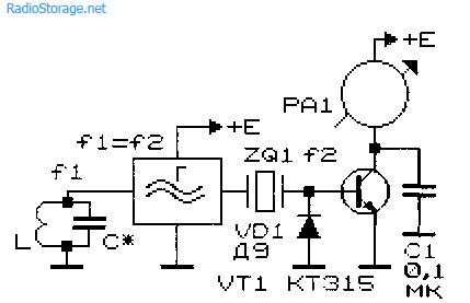
Fig. 9. Concept of metal indicator scheme.
It is made on the VD1 diode, the transistor VT1, the condenser C1 and the milliammeter (microammeter) of the RA1. A quartz resonator is included between the output of the generator and the inlet of the high-frequency maleololtmeter. If the frequency of generation F1 and the frequency of the quartz resonator F2 coincide, the appliance arrow will be at zero. It is worth the generation frequency to change as a result of making a metal object in the search coil field, the appliance arrow will be rejected.
The working frequencies of such metal detectors are usually in the range of 0.1 ... 2 MHz. For the initial installation of the generation frequency of this and other instruments of this purpose, a capacitor of a variable container or a trimmed capacitor connected parallel to the search coil inductance is used.
Typical metal detector with two generators
In fig. 10 is given typical scheme The most common metal detector. Its principle of operation is based on the beats of the frequencies of reference and search generators.

Fig. 10. Metal detector diagram with two generators.

Fig. 11. Schematic diagram of a block generator for a metal detector.
The same type, common for both generators, is shown in Fig. 11. The generator is made according to the well-known scheme of "capacitive three-point". In fig. 10 is shown full scheme Devices. As a search coil L1, a design presented in Fig is used. 2 and 3.
The initial frequencies of the generators should be the same. Outputs from generators through C2 capacitors, SZ (Fig. 10) are fed to a mixer that elames the difference frequency. Dedicated beep through amplifying cascade The transistor VT1 enters the BF1 telephone capsession.
Metal detector on the principle of separation of the generation frequency
Metal detector can work on the principle of separation of the generation frequency. The diagram of such a device is shown in Fig.12. When performing certain conditions (the frequency of the quartz resonator is equal to the resonant frequency of the oscillatory LC-circuit with the search coil) current in the Emitter circuit of the VT1 transistor is minimal.
If the resonant frequency of the LC contour changes noticeably, the generation will be angry, and the instrument readings will increase significantly. Parallel measuring instrument It is recommended to connect a 1 ... 100 NF capacitor with a capacity.

Fig. 12. Metal detector scheme that works on the principle of separation of the generation frequency.
Metal detectors for finding small items
Metal seekers designed to search for small metal objects in everyday life can be assembled according to fig. 13 - 15 schemes.
Such metal detectors also work on the principle of separation of generation: the generator, which includes the search coil of inductance, works in the "critical" mode.
The mode of operation of the generator is installed by the adjusted elements (potentiometers) so that the slightest change The conditions for its operation, for example, the change in the inductance of the search coil, will lead to a breakdown. To indicate the presence / absence of generation, LED level indicators (presence) of alternating voltage are used.
The inductors of the inductance L1 and L2 in the diagram in fig. 13 contain, respectively, 50 and 80 turns of the wire with a diameter of 0.7 ... 0.75 mm. The coils are wound on a ferrite core 600NH with a diameter of 10 mm and a length of 100 ... 140 mm. Generator operating frequency of about 150 kHz.

Fig. 13. Scheme of a simple metal detector on three transistors.

Fig. 14. Scheme of a simple metal detector on four transistors with light indication.
The inductors of the inductance L1 and L2 of another scheme (Fig. 14), made in accordance with the FRG patent (No. 2027408, 1974), have 120 and 45 turns, respectively, when the wire diameter is 0.3 mm [P 7 / 80-61 ]. A ferrite core 400NH or 600NH with a diameter of 8 mm and 120 mm long was used.
Household Metal Seeker
The household metal seeker (BIM) (Fig. 15), which was previously produced by the factory "Radio Corporation" (Moscow), allows you to detect small metal items at a distance of up to 45 mm. The winding data of its inductance coils are unknown, however, when repeating the circuit, it is possible to focus on the data given for instruments of similar purpose (Fig. 13 and 14).
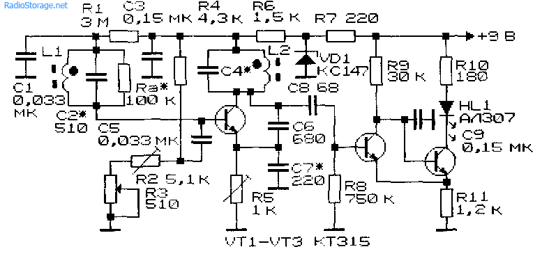
Fig. 15. Scheme of the household Metal Finder.
Literature: Shustov MA Practical scheme engineering (book 1), 2003