
In electronic equipment circuits, one of the most frequently encountered elements is resistance; its other name is resistance. It has a number of characteristics, among which is power. In this article we will talk about resistors, what to do if you do not have an element suitable for the power, and why they burn out.
Resistor characteristics
1. The main parameter of a resistor is the nominal resistance.
2. The second parameter by which it is selected is the maximum (or maximum) power dissipation.
3. Temperature coefficient of resistance - describes how much the resistance changes when its temperature changes by 1 degree Celsius.
4. Permissible deviation from the nominal value. Typically, the spread of resistor parameters from one declared is within 5-10%, it depends on GOST or specifications according to which it is manufactured; there are also precise resistors with a deviation of up to 1%, which usually cost more.
5. The maximum operating voltage depends on the design of the element; in household electrical appliances with a supply voltage of 220V, almost any resistors can be used.
6. Noise characteristics.
7. Maximum ambient temperature. This is the temperature that can occur when the maximum power dissipation of the resistor itself is reached. We'll talk more about this later.
8. Moisture and heat resistance.
There are two more characteristics that beginners most often do not know about:
On low frequencies(for example, within the audio range up to 20 kHz), they do not significantly affect the operation of the circuit. In high-frequency devices, with operating frequencies of hundreds of thousands of hertz and above, even the location of the tracks on the board and their shape make a significant impact.

From the physics course, many people perfectly remember the power formula for electricity, this is: P=U*I
It follows that it linearly depends on current and voltage. The current through the resistor depends on its resistance and the voltage applied to it, that is:
The voltage drop across a resistor (how much voltage remains at its terminals from the voltage applied to the circuit in which it is installed) also depends on the current and resistance:
Now let's explain in simple words what is the power of a resistor and where is it allocated.
Any metal has its own resistivity, this is a value that depends on the structure of that metal itself. When charge carriers (in our case, electrons) flow through a conductor under the influence of an electric current, they collide with the particles that make up the metal.
As a result of these collisions, the flow of current is hampered. To put it very generally, it turns out that the denser the metal structure, the more difficult it is for current to flow (the greater the resistance).
The picture shows an example of a crystal lattice, for clarity.
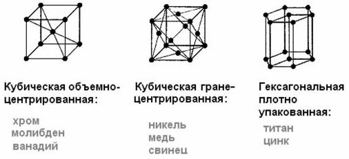
These collisions release heat. Can you think of it as if you were walking through a crowd (lots of resistance) where you were also being pushed, or if you were walking down an empty corridor where you would sweat more?
The same thing happens with metal. Power is released as heat. In some cases, this is bad because it reduces the efficiency of the device. In other situations it is useful property, For example . In incandescent lamps, due to its resistance, the spiral heats up to a bright glow.
But how does this apply to resistors?
The fact is that resistors are used to limit the current when powering any devices or circuit elements, or to set operating modes for semiconductor devices. We described this. From the formula above it will become clear that the current decreases due to a decrease in voltage. Excess voltage can be said to burn in the form of heat on a resistor, and the power is calculated using the same formula as the total power:
Here U is the number of volts "burned" across the resistor, and I is the current that flows through it.
The heat generated by a resistor is explained by the Joule-Lenz law, which relates the amount of heat generated to current and resistance. The greater the first or second, the more heat will be released.
To make it convenient, two more formulas are derived from this formula by substituting Ohm’s law for a section of the chain.
To determine power through the applied voltage to a resistor:
To determine the power through the current flowing through a resistor:
A little practice
For example, let's determine how much power is allocated to a 1 Ohm resistor connected to a 12V voltage source.
First, let's calculate the current in the circuit:
Now the power according to the classic formula:
P=12*12=144 W.
One step in calculations can be avoided if you use the above formulas, let's check it:
P=12^2/1=144/1=144 W.
Everything fits together. The resistor will generate heat with a power of 144W. These are conditional values taken as an example. In practice, you will not find such resistors in electronic equipment, with the exception of large resistances for regulating motors direct current or starting powerful synchronous machines in asynchronous mode.
What types of resistors are there and how are they indicated in the diagram?
The range of resistor powers is standard: 0.05 (0.62) - 0.125 - 0.25 - 0.5 - 1 - 2 - 5
These are typical values of common resistors; there are also larger values or other values. But this series is the most common. When assembling electronics, an electrical circuit diagram is used, starting with the serial number of the elements. It is less common to indicate the nominal resistance, and even less often the nominal resistance and power are indicated.
To quickly determine the power of the resistor, the corresponding UGOs (conditional graphic symbols) according to GOST. Appearance Such designations and their interpretation are presented in the table below.

In general, this data, as well as the name of the specific type of resistor, is indicated in the list of elements, and the permitted tolerance in % is also indicated there.
Externally, they differ in size; the more powerful the element, the larger its size. A larger size increases the area of heat exchange between the resistor and the environment. Therefore, the heat that is released when current passes through the resistance is transferred more quickly to the air (if the environment is air).
This means that the resistor can heat up with more power (emit a certain amount of heat per unit time). When the temperature of the resistance reaches a certain level, first the outer layer with the marking begins to burn out, then the resistive layer (film, wire or something else) burns out.
To give you an idea of how hot a resistor can get, take a look at the heating of the coil of a disassembled powerful resistor (more than 5 W) in a ceramic case.

The characteristics included such a parameter as the permissible ambient temperature. It is indicated for the correct selection of the element. The fact is that since the power of the resistor is limited by its ability to transfer heat and, at the same time, not overheat, but to transfer heat, i.e. When cooling the element by convection or forced air flow, there should be as large a difference as possible between the temperatures of the element and the environment.
Therefore, if it is too hot around the element, it will heat up faster and burn out, even if the electrical power on it is below the maximum dissipated. Normal temperature is 20-25 degrees Celsius.
Continuing this topic:
What to do if there is no resistor of the required power?
A common problem for radio amateurs is the lack of a resistor of the required power. If you have resistors that are more powerful than you need, there is nothing wrong with that, you can install them without hesitation. If only it fits in size. If all the available resistors are less powerful than needed, this is already a problem.
In fact, solving this issue is quite simple. Remember the laws of series and parallel connection of resistors.
1. When resistors are connected in series, the sum of the voltage drops across the entire chain is equal to the sum of the drops across each of them. And the current flowing through each resistor is equal to the total current, i.e. in a circuit of series-connected elements, ONE current flows, but the voltages applied to each of them are DIFFERENT, determined by Ohm’s law for a section of the circuit (see above) Utot = U1 + U2 + U3
2. When resistors are connected in parallel, the voltage drop across all is equal, and the current flowing in each of the branches is inversely proportional to the resistance of the branch. The total current of a chain of parallel-connected resistors is equal to the sum of the currents of each of the branches.
This picture shows all of the above in an easy to remember form.
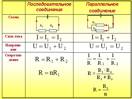
So, just as when connecting resistors in series, the voltage on each of them will decrease, and when connecting resistors in parallel, the current will decrease, then if P = U*I
The power output from each will be reduced accordingly.
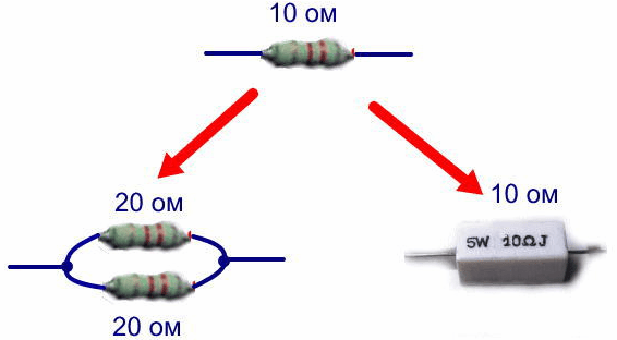
Therefore, if you do not have a 100 ohm 1 W resistor, it can almost always be replaced with 2 50 ohm and 0.5 W resistors connected in series, or 2 200 ohm and 0.5 W resistors connected in parallel.
I wrote “ALMOST ALWAYS” for a reason. The fact is that not all resistors withstand shock currents equally well, in some circuits, for example those associated with charging capacitors large capacity, at the initial moment of time they endure a large shock load, which can damage its resistive layer. Such connections need to be checked in practice or through long calculations and reading technical documentation and specifications for resistors, which almost no one ever does.

Conclusion
The power of a resistor is a value no less important than its nominal resistance. If you do not pay attention to the selection of resistances needed for power, then they will burn out and get very hot, which is bad in any circuit.
When repairing equipment, especially Chinese equipment, do not under any circumstances try to install resistors of lower power; it is better to supply it with a reserve, if it is possible to fit it within the dimensions on the board.
For stable and reliable radio operation electronic device you need to select the power with at least a margin of half of the expected, and preferably 2 times more. This means that if, according to calculations, 0.9-1 W is released on the resistor, then the power of the resistor or their assembly should be no less than 1.5-2 W.
A resistor is an element of an electrical circuit that resists electric current. There are two types of resistors: constant and variable (tuning). When modeling a particular electrical circuit, as well as when repairing electronic products, it becomes necessary to use a resistor of a certain value. Although there are many various denominations constant resistors, in this moment The required one may not be at hand, or a resistor with such a value does not exist. To get out of this situation, you can use both series and parallel connections of resistors. How to correctly calculate and select different resistance values will be discussed in this article.
Series connection of resistors is the most elementary circuit for assembling radio components; it is used to increase the total resistance of the circuit. With a series connection, the resistance of the resistors used simply adds up, but with a parallel connection, it is necessary to calculate using the formulas described below. A parallel connection is necessary to reduce the resulting resistance, as well as to increase power; several resistors connected in parallel have more power than one.
You can see in the photo parallel connection resistors.

Below is a schematic diagram of a parallel connection of resistors.
The total nominal resistance must be calculated according to the following scheme:
R(total)=1/(1/R1+1/R2+1/R3+1/R n).
R1, R2, R3 and Rn are resistors connected in parallel.
When a parallel connection of resistors consists of only two elements, in this case the total nominal resistance can be calculated using the following formula:
R(total)=R1*R2/R1+R2.
R(total) - total resistance;
R1, R2 are resistors connected in parallel.
In radio engineering, there is the following rule: if a parallel connection of resistors consists of elements of the same value, then the resulting resistance can be calculated by dividing the resistor value by the number of connected resistors:
R(total) - total resistance;
R is the value of a parallel connected resistor;
N is the number of connected elements.

It is important to consider that with a parallel connection, the resulting resistance will always be lower than the resistance of the smallest resistor.
Let's give a practical example: take three resistors with the following nominal resistance values: 100 Ohm, 150 Ohm and 30 Ohm. Let's calculate the total resistance using the first formula:
R(total)=1/(1/100+1/150+1/30)=1/(0.01+0.007+0.03)=1/0.047=21.28 Ohm.
After calculating the formula, we see that a parallel connection of resistors consisting of three elements, with the smallest nominal value of 30 ohms, results in a total resistance in the electrical circuit of 21.28 ohms, which is lower than the smallest nominal resistance in the circuit by almost 30 percent.
Parallel connection of resistors is most often used in cases where it is necessary to obtain resistance with greater power. In this case, it is necessary to take resistors of the same power and with the same resistance. The resulting power in this case is calculated by multiplying the power of one resistance element by the total number of parallel connected resistors in the circuit.
For example: five resistors with a nominal value of 100 Ohms and a power of 1 W each, connected in parallel, have a total resistance of 20 Ohms and a power of 5 W.
When connecting the same resistors in series (the power also adds up), we get a resulting power of 5 W, the total resistance will be 500 Ohms.
For any radio amateur, a resistor is a part that is needed in almost every the simplest scheme. In a trivial situation, resistance is a coil of wire that conducts poorly electricity, constantan is often used as a metal.
For a variable or constant resistor, for experimental purposes, you can use graphite, the rod of which is located inside a simple pencil. It has good electrical conductivity. Therefore, for a homemade resistor you need a thin layer of it, which can be applied to paper and combine the required resistance of up to several hundred kilo-ohms.
Based on the properties of graphite, we will build a working model of a resistor on paper. In this case, we will proceed from simple arithmetic: the longer the conductor, the greater its electrical resistance.
In the photo below the indicator shows in megaohms.
The display shows that a strip of graphite, which is 2 times longer, has, accordingly, 2 times the resistance index. Please note that the width of the stripes is the same.

A wide conductor has less resistance.

A strip of graphite applied to paper can easily be turned into an experimental variable resistor, or, otherwise, let’s call it a rheostat.

This idea is perfect for physics lessons. Material used from the site samodelnie.ru
(fixed resistors), and in this part of the article we’ll talk about, or variable resistors.
Resistors variable resistance , or variable resistors are radio components whose resistance can be change from zero to nominal value. They are used as gain controls, volume and tone controls in sound-reproducing radio equipment, are used for precise and smooth adjustment of various voltages and are divided into potentiometers And tuning resistors.
Potentiometers are used as smooth gain controls, volume and tone controls, and are used for smooth adjustment various voltages, and are also used in tracking systems, in computing and measuring devices, etc.

Potentiometer called an adjustable resistor having two permanent terminals and one movable. The permanent terminals are located at the edges of the resistor and are connected to the beginning and end of the resistive element, forming the total resistance of the potentiometer. The middle terminal is connected to a movable contact, which moves along the surface of the resistive element and allows you to change the resistance value between the middle and any extreme terminal.
The potentiometer is a cylindrical or rectangular body, inside of which there is a resistive element made in the form of an open ring, and a protruding metal axis, which is the handle of the potentiometer. At the end of the axis there is a current collector plate (contact brush) that has reliable contact with the resistive element. Reliable contact of the brush with the surface of the resistive layer is ensured by the pressure of a slider made of spring materials, for example, bronze or steel.


When the knob is rotated, the slider moves along the surface of the resistive element, as a result of which the resistance changes between the middle and extreme terminals. And if voltage is applied to the extreme terminals, then an output voltage is obtained between them and the middle terminal.
The potentiometer can be schematically represented as shown in the figure below: the outer terminals are designated by numbers 1 and 3, the middle one is designated by number 2.

Depending on the resistive element, potentiometers are divided into non-wire And wire.
1.1 Non-wire.
In non-wire potentiometers, the resistive element is made in the form horseshoe-shaped or rectangular plates made of insulating material, on the surface of which a resistive layer is applied, which has a certain ohmic resistance.
Resistors with horseshoe-shaped resistive element has a round shape and rotational movement of the slider with a rotation angle of 230 - 270°, and resistors with rectangular the resistive element has a rectangular shape and the translational movement of the slider. The most popular resistors are the types SP, OSB, SPE and SP3. The figure below shows a SP3-4 type potentiometer with a horseshoe-shaped resistive element.


The domestic industry produced potentiometers of the SPO type, in which the resistive element is pressed into an arcuate groove. The body of such a resistor is made of ceramic, and for protection against dust, moisture and mechanical damage, and also for electrical shielding purposes, the entire resistor is covered with a metal cap.
Potentiometers of the SPO type have high wear resistance, are insensitive to overloads and are small in size, but they have a drawback - the difficulty of obtaining nonlinear functional characteristics. These resistors can still be found in old domestic radio equipment.

1.2. Wire.
IN wire In potentiometers, the resistance is created by a high-resistance wire wound in one layer on a ring-shaped frame, along the edge of which a moving contact moves. To obtain reliable contact between the brush and the winding, the contact track is cleaned, polished, or ground to a depth of 0.25d.


The structure and material of the frame is determined based on the accuracy class and the law of change in resistance of the resistor (the law of change in resistance will be discussed below). The frames are made of a plate, which, after winding the wires, is rolled into a ring, or a finished ring is taken, on which the winding is laid.
For resistors with an accuracy not exceeding 10 - 15%, the frames are made of a plate, which, after winding the wires, is rolled into a ring. The material for the frame is insulating materials such as getinax, textolite, fiberglass, or metal - aluminum, brass, etc. Such frames are easy to manufacture, but do not provide precise geometric dimensions.
Frames from the finished ring are manufactured with high precision and are mainly used for the manufacture of potentiometers. The material for them is plastic, ceramics or metal, but the disadvantage of such frames is the difficulty of winding, since special equipment is required to wind it.
The winding is made of wires made of alloys with high specific electrical resistance, for example, constantan, nichrome or manganin in enamel insulation. For potentiometers, wires made of special alloys based on noble metals are used, which have reduced oxidation and high wear resistance. The diameter of the wire is determined based on the permissible current density.
2. Basic parameters of variable resistors.
The main parameters of resistors are: total (nominal) resistance, form of functional characteristics, minimum resistance, rated power, rotational noise level, wear resistance, parameters characterizing the behavior of the resistor under climatic influences, as well as dimensions, cost, etc. However, when choosing resistors, attention is most often paid to the nominal resistance and less often to the functional characteristics.
2.1. Nominal resistance.
Nominal resistance resistor is indicated on its body. According to GOST 10318-74, the preferred numbers are 1,0 ; 2,2 ; 3,3 ; 4,7 Ohm, kiloohm or megaohm.
For foreign resistors, the preferred numbers are 1,0 ; 2,0 ; 3,0 ; 5.0 Ohm, kiloohm and megaohm.
Permissible deviations of resistances from the nominal value are set within ±30%.
The total resistance of the resistor is the resistance between the outer terminals 1 and 3.

2.2. Form of functional characteristics.
Potentiometers of the same type may differ functional characteristic, which determines the law by which the resistance of the resistor between the extreme and middle terminals changes when the resistor knob is turned. According to the form of functional characteristics, potentiometers are divided into linear And nonlinear: y linear magnitude resistance changes in proportion to the movement of the current collector; for nonlinear ones it changes according to a certain law.
There are three basic laws: A— Linear, B– Logarithmic, IN— Reverse Logarithmic (Exponential). So, for example, to regulate the volume in sound-reproducing equipment, it is necessary that the resistance between the middle and extreme terminals of the resistive element varies according to inverse logarithmic law (B). Only in this case is our ear able to perceive a uniform increase or decrease in volume.
Or in measuring instruments, for example, generators audio frequency, where variable resistors are used as frequency-setting elements, it is also required that their resistance varies according to logarithmic(B) or inverse logarithmic law. And if this condition is not met, then the generator scale will be uneven, which will make it difficult to accurately set the frequency.
Resistors with linear characteristic (A) are used mainly in voltage dividers as adjustment or trimmers.
The dependence of the change in resistance on the angle of rotation of the resistor handle for each law is shown in the graph below.

To obtain the desired functional characteristics, major changes are not made to the design of potentiometers. For example, in wirewound resistors, the wires are wound with varying pitches or the frame itself is made of varying width. In non-wire potentiometers, the thickness or composition of the resistive layer is changed.

Unfortunately, adjustable resistors have relatively low reliability and limited service life. Often, owners of audio equipment operated long time, you can hear rustling and crackling sounds from the speaker when turning the volume control. The reason for this unpleasant moment is a violation of the contact of the brush with the conductive layer of the resistive element or wear of the latter. The sliding contact is the most unreliable and vulnerable point of a variable resistor and is one of the main reasons for part failure.
3. Designation of variable resistors on diagrams.
On circuit diagrams Variable resistors are designated in the same way as constant ones, only an arrow directed towards the middle of the case is added to the main symbol. The arrow indicates regulation and at the same time indicates that this is the middle output.

Sometimes situations arise when requirements for reliability and service life are imposed on a variable resistor. In this case smooth regulation is replaced by a step one, and a variable resistor is built on the basis of a switch with several positions. Constant resistance resistors are connected to the switch contacts, which will be included in the circuit when the switch knob is turned. And in order not to clutter the diagram with the image of a switch with a set of resistors, only the symbol of a variable resistor with a sign is indicated step regulation. And if there is a need, then the number of steps is additionally indicated.

To control volume and timbre, recording level in stereo sound-reproducing equipment, to control frequency in signal generators, etc. apply dual potentiometers, the resistance of which changes simultaneously when turning general axis (engine). In the diagrams, the symbols of the resistors included in them are placed as close to each other as possible, and the mechanical connection that ensures the simultaneous movement of the sliders is shown either with two solid lines or with one dotted line.

The belonging of resistors to one double block is indicated according to their positional designation in the electrical diagram, where R1.1 is the first resistor of the dual variable resistor R1 in the circuit, and R1.2- second. If the resistor symbols are at a great distance from each other, then the mechanical connection is indicated by segments of a dotted line.

The industry produces dual variable resistors, in which each resistor can be controlled separately, because the axis of one passes inside the tubular axis of the other. For such resistors, there is no mechanical connection that ensures simultaneous movement, therefore it is not shown on the diagrams, and membership of a dual resistor is indicated according to the positional designation in the electrical diagram.
Portable household audio equipment, such as receivers, players, etc., often use variable resistors with a built-in switch, the contacts of which are used to supply power to the device circuit. For such resistors, the switching mechanism is combined with the axis (handle) of the variable resistor and, when the handle reaches the extreme position, it affects the contacts.

As a rule, in the diagrams, the contacts of the switch are located near the power source in the break of the supply wire, and the connection between the switch and the resistor is indicated by a dotted line and a dot, which is located at one of the sides of the rectangle. This means that the contacts close when moving from a point, and open when moving towards it.
4. Trimmer resistors.
Trimmer resistors are a type of variable and serve for one-time and fine tuning radio-electronic equipment during its installation, adjustment or repair. As tuning resistors, both conventional type variable resistors with a linear functional characteristic, the axis of which is made “under a slot” and equipped with a locking device, and specially designed resistors with increased accuracy setting the resistance value.

For the most part trim resistors of a special design are made in a rectangular shape with flat or circular resistive element. Resistors with a flat resistive element ( A) have a translational movement of the contact brush, carried out by a micrometric screw. For resistors with a ring resistive element ( b) the contact brush is moved by a worm gear.

For heavy loads, open cylindrical resistor designs are used, for example, PEVR.

In circuit diagrams, tuning resistors are designated in the same way as variables, only instead of the control sign, the tuning control sign is used.

5. Inclusion of variable resistors in an electrical circuit.
IN electrical diagrams variable resistors can be used as rheostat(adjustable resistor) or as potentiometer(voltage divider). If it is necessary to regulate the current in an electrical circuit, then the resistor is turned on with a rheostat; if there is voltage, then it is turned on with a potentiometer.
When the resistor is turned on rheostat the middle and one extreme output are used. However, such inclusion is not always preferable, since during the regulation process, the middle terminal may accidentally lose contact with the resistive element, which will entail an unwanted break in the electrical circuit and, as a consequence, possible failure of the part or the electronic device as a whole.

To prevent accidental breakage of the circuit, the free terminal of the resistive element is connected to a moving contact, so that if contact is broken electrical circuit always remained closed.

In practice, turning on a rheostat is used when they want to use a variable resistor as an additional or current-limiting resistance.
When the resistor is turned on potentiometer All three pins are used, which allows it to be used as a voltage divider. Let's take, for example, a variable resistor R1 with such a nominal resistance that it will extinguish almost all of the power source voltage coming to the HL1 lamp. When the resistor knob is twisted to the highest position in the diagram, the resistance of the resistor between the upper and middle terminals is minimal and the entire voltage of the power source is supplied to the lamp, and it glows at full heat.

As you move the resistor knob down, the resistance between the upper and middle terminals will increase, and the voltage on the lamp will gradually decrease, causing it to not glow at full intensity. And when the resistance of the resistor reaches maximum value, the voltage on the lamp will drop to almost zero and it will go out. It is by this principle that volume control in sound-reproducing equipment occurs.
The same voltage divider circuit can be depicted a little differently, where the variable resistor is replaced by two constant resistors R1 and R2.

Well, that’s basically all I wanted to say about variable resistance resistors. In the final part, we will consider a special type of resistors, the resistance of which changes under the influence of external electrical and non-electrical factors -.
Good luck!
Literature:
V. A. Volgov - “Parts and components of radio-electronic equipment”, 1977
V. V. Frolov - “The language of radio circuits”, 1988
M. A. Zgut - “ Legend and radio circuits", 1964